Use 85 to 90% of Deck Beam Spans: A Homeowner's Code First Plan
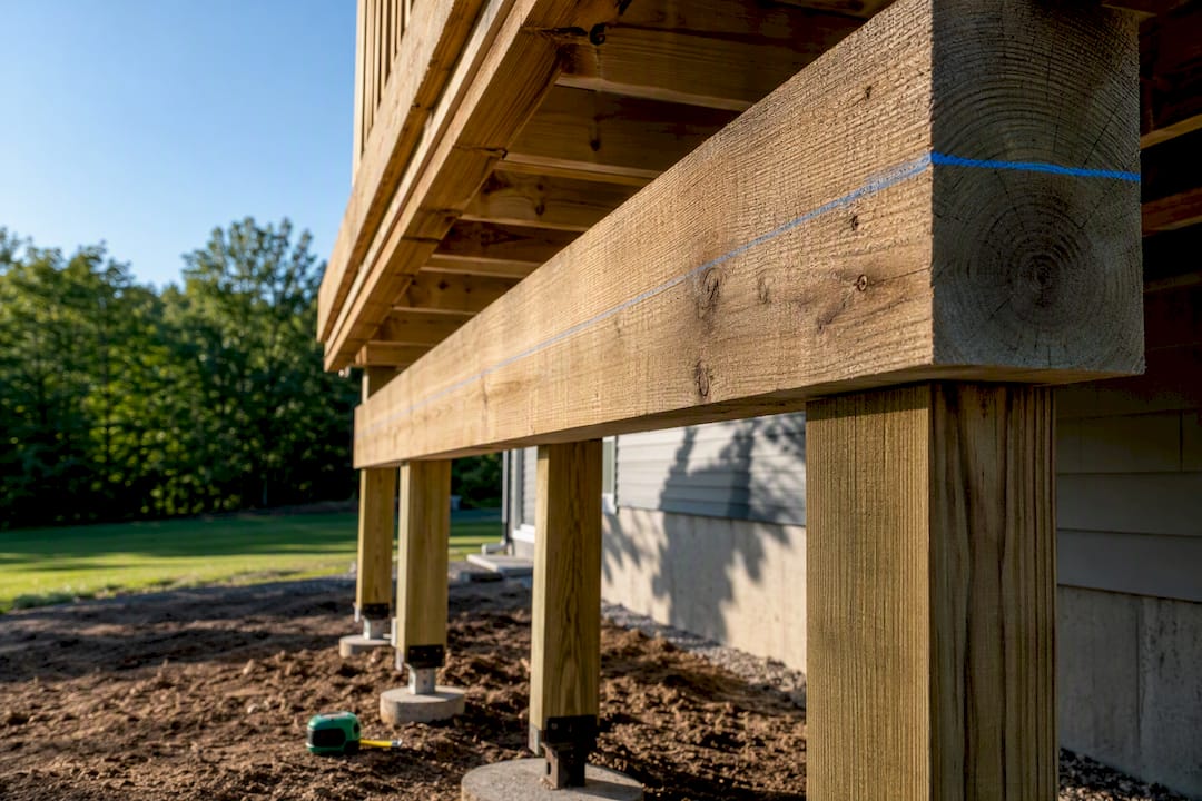
How far a deck beam can span depends on beam size and ply count, wood species, and the tributary width of the joists it carries. A 2-ply 2×10 in Southern Pine carrying a 6-foot tributary width spans about 8’-0" under IRC R507.5, while a 3-ply 2×12 under the same conditions can reach roughly 11’-3". Design to somewhat less than the tabulated maximum to leave room for real-world moisture movement and construction tolerances.
TL;DR:
- Using a 2-ply 2x10 Southern Pine beam generally limits spans to around 8 feet for typical deck loads, regardless of tributary width.
- Snow loads exceeding 40 psf require referencing specific tables for higher ground snow regions, which reduce allowable spans by up to 25%.
- Effective joist span and tributary width must be accurately measured and adjusted for cantilevers to select the correct beam size and margin.
- Designing to 85-90% of the tabulated maximum span provides a safety margin to account for moisture, long-term deflection, and material variability.
- For spans over 12 feet or supporting concentrated loads such as hot tubs, engineers should consider engineered beams like LVL or PSL instead of sawn lumber.
Table of Contents
- How Do You Read Deck Beam Span Charts?
- How Do You Calculate Tributary Width for a Deck Beam?
- How Do You Interpolate Between Beam Span Table Values?
- What Fastening and Cantilever Rules Apply to Deck Beams?
- When Should You Switch to Engineered Beams Instead of Sawn Lumber?
- A Worked Example: Sizing a Deck Beam from Scratch
- What Should You Check Before Buying Lumber?
- How Do Live Load and Snow Load Combine in Beam Sizing?
- What Deflection Limits Keep a Deck Beam from Feeling Bouncy?
- Do Treatments and Coatings Affect Beam Span Capacity?
- How Do Moisture, Temperature, and Insects Affect Beam Selection?
- Why Do Deck Beams Need Lateral Bracing?
- How Property Improvement Estimator Supports Code-Aware Deck Planning
- Turn Your Beam Sizing Into a Permit-Ready Plan
- Where the Beam Span Numbers Come From
- The Gap Between Code Minimums and a Deck That Feels Right
- Sources
How Do You Read Deck Beam Span Charts?
The IRC’s prescriptive beam tables are built around three inputs: beam size and ply count, wood species, and the tributary width of the joists resting on the beam. Get any one of those wrong and the whole lookup falls apart, so it’s worth understanding what each column actually represents before you touch a chart.
IRC R507.5 provides Table R507.5(1) for a 40 psf live load plus 10 psf dead load baseline, using Southern Pine No. 2 built-up beams as the reference species. Every other common framing species gets a multiplier applied to those Southern Pine numbers: Douglas Fir-Larch at 0.95, and Hem-Fir or Spruce-Pine-Fir at 0.90. So a beam that spans 10 feet in Southern Pine spans about 9’-6" in DF-L and about 9’-0" in Hem-Fir or SPF, using the same size and tributary width.
Here’s a condensed version of the Southern Pine No. 2 table at 40 psf, showing maximum post-to-post beam spans by ply count, beam size, and tributary width (the joist span carried by the beam, measured from ledger or adjacent beam to this beam, or half that distance on each side for a freestanding beam in the middle of a deck):
These figures come from the DeckMath beam sizing guide, which reproduces the Table R507.5(1) logic for Southern Pine No. 2 lumber. Treat this as a planning reference, not a substitute for pulling the actual code table for your jurisdiction, since local amendments occasionally tighten these numbers.
Snow-load tables change everything in cold climates. IRC 2021 added dedicated beam-span tables for 50, 60, and 70 psf ground snow loads, in addition to the 40 psf baseline table most builders default to. If your jurisdiction’s ground snow load exceeds 40 psf (check your local building department or the ASCE 7 map for your area), you need to reference Table R507.5(2), (3), or (4) instead of the standard one. Spans in the 50 to 70 psf tables run roughly 10 to 25% shorter than the 40 psf baseline for the same beam and tributary width, so pulling the wrong table can leave you undersized without realizing it.
A couple of rules of thumb worth memorizing: a 2×10, 2-ply beam in Southern Pine rarely clears much past 9 feet regardless of tributary width, and a 3-ply 2×12 is usually your practical ceiling before engineered lumber starts making more sense. If your span calculations keep landing near or beyond those numbers, that’s your cue to either add a post, upsize the beam, or move to engineered material, which the comparative section below covers.
How Do You Calculate Tributary Width for a Deck Beam?
Tributary width is the portion of the deck’s load that funnels into a specific beam. It’s not the same as the beam’s actual span between posts. Confusing the two is the single most common beam-sizing mistake DIYers make.
For a ledger-attached deck, tributary width is measured from the ledger to the beam if the beam sits at the outer edge, or as the average of the two joist spans on either side if the beam sits in the middle of the joist run. For a freestanding deck with a beam on each end, each beam typically carries half the total joist span, since the load splits roughly evenly between the two supports.
The effective joist span matters just as much as tributary width, and it’s the piece most guides skip. If your actual joist span doesn’t line up with a table column, or if your joists cantilever past the beam rather than stopping right at it, JLC’s guide to right-sizing deck beams explains how Table R507.5(5) joist-span factors adjust for that. A joist that cantilevers over the beam actually reduces the effective span the beam has to account for, which can work in your favor.
Here’s the sequence to follow:
- Measure your actual joist span from ledger to beam (or beam to beam), in feet.
- Note whether joists cantilever past the beam, and by how much.
- Apply the appropriate joist-span factor from Table R507.5(5) if a cantilever is present, to get your effective joist span.
- Determine tributary width using the ledger-to-beam or split-span method above.
- Match the effective joist span and tributary width to the correct column in your beam-span table.
Say you’ve got a joist span of 12 feet running from a ledger to a beam, with no cantilever. Your effective joist span is just 12 feet, no adjustment needed. But if that same joist cantilevers 2 feet past the beam, the effective span typically drops because the cantilever helps counterbalance the load on the beam side, sometimes by a foot or more depending on the ratio.
When your numbers fall between table columns, round up to the next tributary width rather than down. It’s a small margin of conservatism that costs you almost nothing in material but keeps you clearly inside the prescriptive path instead of guessing at an interpolated number an inspector might question.
How Do You Interpolate Between Beam Span Table Values?
Deck beam tables give you discrete columns, usually in 2-foot tributary-width increments, but your actual project rarely lines up neatly with those numbers. You’ve got three practical ways to handle the gap.
Round to the conservative side. If your tributary width falls between the 6-foot and 8-foot columns, use the 8-foot value. This is the simplest and safest approach, and it’s what most building departments expect to see on a permit submission since it requires no extra math to verify.
Use straight-line interpolation. If you want a tighter number instead of over-building, calculate proportionally between two known values. Say your tributary width is 7 feet, sitting between the 6-foot span (9’-0" for a 2×10 3-ply) and the 8-foot span (8’-8"). The difference between those two spans is 4 inches over a 2-foot tributary change, so at 7 feet you’re roughly 2 inches short of the 6-foot number, landing around 8’-10".
Run the actual bending-moment math. For anyone comfortable with basic engineering formulas, the DeckMath beam size calculator applies the same bending-moment and section-modulus checks that generate the tables in the first place, letting you solve for your exact inputs rather than approximating between columns.
- Match your effective joist span to the table’s joist-span axis, not your beam’s own length.
- Match tributary width to the table’s tributary-width axis, always rounding up when in doubt.
- Never mix species multipliers with tributary interpolation in the same step. Adjust for species first, then interpolate.
- Cross-check your final number against a second source, like up.codes’ reproduction of Table R507.5, before finalizing lumber orders.
Pro Tip: Design to somewhat less than the full tabulated maximum to allow for lumber sag from moisture cycling, improving long-term deck stability and comfort.
What Fastening and Cantilever Rules Apply to Deck Beams?
Inspectors reject more decks over fastening details than over beam sizing itself, mostly because the nailing pattern is easy to shortcut and hard to spot without close inspection.
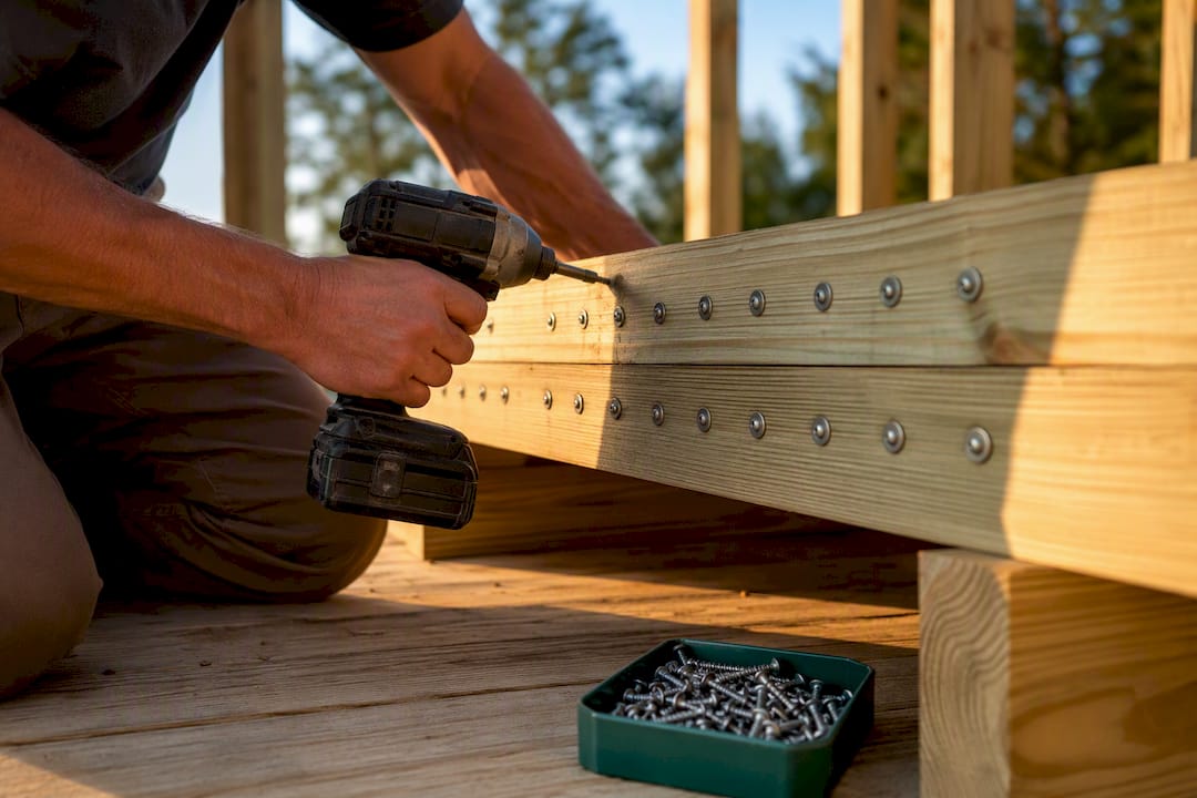
IRC R507.5.2 requires built-up beams to be fastened with two rows of 10d nails (3 inches by 0.128 inches), spaced no more than 16 inches on center along each edge of the beam. Structural screws of equivalent capacity are also acceptable in most jurisdictions, and many builders prefer them for the cleaner installation. For 3-ply beams, through-bolting or heavy structural connectors are often specified in addition to nailing, since three layers of lumber nailed from one face alone don’t always transfer load evenly across all plies, according to DeckMath’s construction guidance.
Post bearing is the other detail inspectors scrutinize closely. A beam can sit on top of a post using a post cap connector, which is the more forgiving and widely accepted method, or it can be notched into the top of a 6×6 post, which requires a minimum 1.5-inch bearing surface on remaining wood. Notched connections are not permitted on 4×4 posts, since removing material from a post that size leaves too little bearing area to carry the load safely. If your design calls for notched bearing, plan on 6×6 posts from the start.
Beam cantilevers work differently than joist cantilevers, and mixing the two rules up is a common error. A beam can cantilever past its end post by up to one-fourth of its allowable backspan, per R507.5.1. So a beam with a 10-foot span between posts can cantilever up to 2’-6" beyond the last post. Joist cantilevers follow a separate ratio entirely, so don’t assume the same fraction applies to both.
- Two rows of 10d nails (3" × 0.128") or equivalent screws, 16 inches on center, along each edge.
- 3-ply beams typically need through-bolts or heavy connectors in addition to nailing.
- Post caps work with 4×4 or 6×6 posts; notched bearing requires 6×6 minimum.
- Beam cantilevers max out at one-fourth of the allowable backspan, measured from the last support.
When Should You Switch to Engineered Beams Instead of Sawn Lumber?
Sawn lumber stops being the efficient choice somewhere around a 12-foot span, and the reason comes down to basic beam mechanics rather than a code preference.
Bending moment in a simply supported beam follows the formula M = wL²/8, meaning the moment grows with the square of the span. Double the span and you quadruple the bending demand on the beam, per the DeckMath calculator’s underlying math. That’s why a beam that comfortably handles 8 feet needs far more than double the material to handle 16 feet. At some point, stacking more 2× plies together stops being practical, and engineers observe that sawn lumber efficiency drops sharply once you cross roughly 12 feet, according to structural comparisons of sawn versus engineered lumber.
That’s the point where laminated veneer lumber (LVL) or parallam PSL beams usually take over. They’re manufactured with tighter dimensional tolerances, they don’t twist or check the way sawn lumber can, and their section properties let them span farther without adding ply after ply of dimensional lumber.
You should be looking hard at engineered options when:
- Your calculated span pushes past 12 feet even with a 3-ply 2×12, and adding another post isn’t feasible for the layout you want.
- You’re supporting a hot tub, outdoor kitchen, or other concentrated point load that exceeds the standard 40 psf assumption baked into the prescriptive tables.
- Moisture exposure or long-term deflection sensitivity make dimensional stability more important than upfront material cost.
Manufacturer span tables for LVL and PSL products are specific to that manufacturer’s product line, so you can’t substitute a generic sawn-lumber table for an engineered beam. Some jurisdictions also require a structural engineer’s (SE) letter for PSL or engineered installations outside standard prescriptive limits, particularly for longer spans or unusual loading. That adds cost and time, but it’s often cheaper overall than an oversized built-up beam that eats into headroom or requires an extra row of footings you didn’t want.
Pro Tip: If you’re framing for a hot tub, treat it as a point load problem, not a uniform-load problem. The 40 psf prescriptive tables assume evenly distributed weight across the deck, and a filled hot tub concentrates thousands of pounds onto a small footprint the tables never anticipated. Homeowners planning an outdoor kitchen layout on a deck should run the same check before finalizing beam size.
A Worked Example: Sizing a Deck Beam from Scratch
Let’s walk through an actual project so you can see how the pieces fit together.
The inputs: a ledger-attached deck with a 12-foot joist span, no cantilever on the joists, desired post spacing of 8 feet, Southern Pine framing lumber, and the standard 40 psf live load plus 10 psf dead load baseline (no elevated snow load in this example).
- Confirm effective joist span. Since there’s no joist cantilever, the effective joist span equals the actual span: 12 feet.
- Determine tributary width. The beam sits at the outer edge of the deck opposite the ledger, so it carries the full 12-foot joist span as its tributary width.
- Pick a starting beam size. Try a 3-ply 2×12 first, since 12-foot tributary widths push toward the upper end of what dimensional lumber handles well.
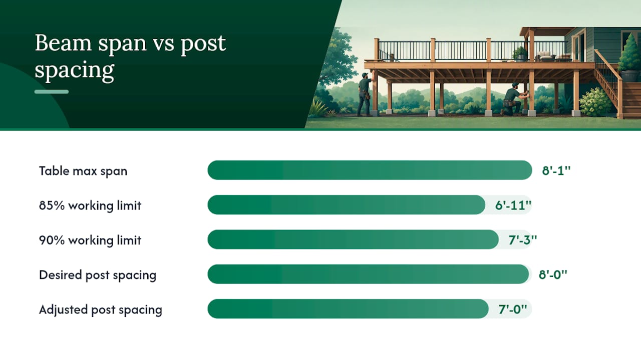
- Look up the table value. At a 12-foot tributary width, a 3-ply 2×12 in Southern Pine spans roughly 8’-1" per the condensed table above, that’s well short of the 8-foot post spacing you wanted.
- Identify the shortfall. You need at least 8 feet of span at a 12-foot tributary, and the 3-ply 2×12 only delivers 8’-1", which technically clears it but leaves almost no design margin.
- Apply the margin recommendation. Designing to 85 to 90% of tabulated span means treating that 8’-1" maximum as an effective working limit closer to 6’-11" to 7’-3". Your 8-foot post spacing now fails the margin check even though it technically passes the raw table number.
- Consider your options. You could tighten post spacing to 7 feet to stay inside the safety margin, or move to an engineered LVL beam sized for the full 8-foot spacing with room to spare.
- Check the cantilever, if any. If the beam needs to cantilever past an end post, confirm it doesn’t exceed one-fourth of 8’-1", which caps the cantilever at about 2 feet.
- Verify fastening. Two rows of 10d nails at 16 inches on center along each edge, with through-bolts added since this is a 3-ply beam.
- Confirm post bearing. A post cap connector on a 6×6 post handles this load cleanly without notching, keeping the bearing detail simple for inspection.
This example shows exactly why the 85 to 90% margin recommendation matters so much in practice: a beam that “passes” the raw table can still fail your comfort and long-term serviceability standard once you build in a realistic safety cushion. In this case, tightening post spacing to 7 feet solved the problem without changing the lumber, though switching to a 1¾-inch LVL beam would have handled the full 8-foot spacing with room left over.
Once the beam size and post spacing are locked in, the remaining steps are procedural: verify footing size against your soil bearing capacity and local frost depth, confirm your fastening schedule matches R507.5.2, and document the final span and post layout for your permit drawing. A design that lands comfortably inside the 85 to 90% margin, with fastening and bearing details spelled out, is what most building departments want to see on a first submission, with far less back-and-forth than a design that just barely clears the raw table maximum.
What Should You Check Before Buying Lumber?
Run through this list before you order material or call a contractor for quotes.
- Measure your actual joist span and confirm whether joists cantilever past the beam.
- Calculate tributary width using the ledger-to-beam or split-span method for freestanding decks.
- Select a beam size and ply count from the appropriate span table for your tributary width.
- Apply the correct species multiplier if you’re not using Southern Pine (DF-L at 0.95, Hem-Fir or SPF at 0.90).
- Confirm you’re using the right load table. Check your local ground snow load and reference the 50, 60, or 70 psf table if it applies to your area.
- Build in the 85 to 90% design margin rather than designing to the raw table maximum.
- Verify fastening requirements: two rows of 10d nails or equivalent screws at 16 inches on center, plus through-bolts for 3-ply beams.
- Confirm post bearing details, post cap versus notched 6×6, before finalizing your post size.
- Check footing depth and bearing capacity against local frost line and soil conditions.
If your numbers keep failing even after adjusting post spacing, that’s the signal to add an intermediate post or switch to LVL or PSL rather than forcing a sawn-lumber solution that doesn’t fit. Homeowners planning anything beyond a basic rectangular deck, elevated structures, unusual point loads, or heavy snow country, benefit from running their layout through a proper deck cost calculator before committing to a specific beam size, since post count and beam size both drive material cost significantly.
How Do Live Load and Snow Load Combine in Beam Sizing?
Beam span tables don’t just account for the weight of people and furniture. They’re built around a specific combination of live load and dead load, and in snow country, snow load gets added into that equation rather than treated separately.
The 40 psf baseline table assumes 40 psf live load plus 10 psf dead load, a combination that reflects typical residential deck use in regions without significant snow accumulation. Once ground snow loads exceed that baseline, the IRC’s dedicated snow-load tables at 50, 60, and 70 psf replace the standard table entirely rather than getting added on top of it. You don’t stack snow load onto the 40 psf table yourself. You look up your ground snow load, find the matching table, and read spans directly from it.
This matters because snow load isn’t a seasonal afterthought in the mountain West or northern states. If you live somewhere that regularly sees snow loads and you’ve been using the standard 40 psf table out of habit or because it’s the one that shows up first in a search result, that’s worth double-checking against your local building department’s design snow load before you cut any lumber.
What Deflection Limits Keep a Deck Beam from Feeling Bouncy?
Span tables tell you the maximum length a beam can carry without breaking. Deflection limits tell you how much it can bend without feeling unpleasant to stand on, and that’s a separate check baked into how the tables were built in the first place.
Most residential deck beams are governed by an L/360 deflection limit under live load, meaning the beam can’t sag more than its span divided by 360 under the weight it’s designed to carry. For a 10-foot beam, that works out to a maximum deflection of about a third of an inch. It sounds small, but it’s the difference between a deck that feels solid and one that has a noticeable spring to it when someone walks across.
The prescriptive IRC tables already build this deflection check into their span limits, so if you’re following the table correctly, you’re automatically inside the deflection requirement too. Where this becomes relevant for homeowners is in the margin conversation covered earlier. Beams that just barely meet the table maximum are also just barely meeting the deflection limit, which is part of why designing to 85 to 90% of tabulated span improves comfort, not just long-term strength. A beam with some margin built in deflects noticeably less than one running right at its ceiling, even though both technically pass code.
Do Treatments and Coatings Affect Beam Span Capacity?
Pressure-treated lumber is the default choice for deck beams exposed to weather, and the treatment process itself doesn’t reduce the structural values used in the span tables. The IRC’s prescriptive tables assume standard preservative-treated Southern Pine or equivalent species, so a properly treated beam performs to the same span values as an untreated one of the same grade.
Where treatment matters is fastener compatibility and long-term moisture behavior, not raw bending strength. Modern preservative treatments, particularly newer copper-based formulations, are more corrosive to certain fasteners than older treatments were. Using the wrong nail or screw coating can lead to accelerated corrosion at exactly the connection points, the beam-to-post fastening and ply-to-ply nailing, that carry the most load. Always confirm your fasteners and connectors are rated for contact with treated lumber, since a corroded fastener years down the line effectively reduces your beam’s real-world capacity even though the wood itself is fine.
Surface coatings and sealants applied after construction, stains, water repellents, and similar products, don’t materially change span capacity either. Their main structural benefit is slowing moisture absorption and the swelling or checking that comes with wet-dry cycling. A well-sealed beam holds its dimensional stability better over time, which indirectly supports the long-term serviceability margin discussed earlier, but it’s not something you factor into the initial span calculation itself.
How Do Moisture, Temperature, and Insects Affect Beam Selection?
Environmental exposure doesn’t change the numbers in a span table, but it changes how reliably a beam performs at those numbers over the life of the deck.
Moisture is the biggest long-term factor. Wood that stays consistently damp, from poor drainage, ground contact, or inadequate ventilation underneath a low deck, swells, shrinks, and eventually loses some of its load-carrying capacity as fibers break down.
Temperature swings compound the moisture issue rather than acting independently. Repeated freeze-thaw cycles in wet lumber accelerate checking and splitting, particularly at fastener locations where water tends to collect. Beams in climates with hard winters benefit from slightly more conservative sizing and from fasteners and hardware rated for exterior exposure, since a corroded connector in a freeze-thaw environment fails faster than the wood around it.
Insect resistance is a regional consideration that varies enormously depending on where you live. In areas with significant termite or carpenter ant pressure, pressure-treated lumber’s insect resistance becomes a functional requirement rather than a nice-to-have, and ground-contact rated lumber should be used for any beam within 6 inches of soil or in an unventilated crawl space. None of this changes the span number itself, but skipping it shortens the usable life of a beam that was otherwise sized correctly on paper.
Why Do Deck Beams Need Lateral Bracing?
A beam sized correctly for bending can still fail in a way the span tables don’t directly address: twisting or rolling sideways under load, a failure mode engineers call lateral-torsional buckling.
Tall, narrow beams, like a single 2×12 standing on edge, are more prone to this than wider, shorter cross-sections, since the beam has less resistance to rotating along its length when it’s not braced. Joists nailed perpendicular to the top of the beam at regular intervals provide most of the lateral bracing a deck beam needs in typical residential construction, which is one reason the standard fastening schedule connecting joists to beams matters as much structurally as it does for load transfer.
Beams that span longer distances or carry unusually tall, narrow profiles benefit from additional blocking between joists near the beam line, particularly at the ends where the beam meets its posts. This keeps the beam from rotating at its most vulnerable points. Multi-ply built-up beams get some inherent resistance to twisting just from their wider combined cross-section compared to a single 2× member, which is one more reason built-up construction remains the standard prescriptive approach rather than single-ply lumber for anything beyond very short spans.
If you’re working with an engineered beam, LVL or PSL, check the manufacturer’s bracing requirements specifically, since some engineered products have different lateral stability characteristics than sawn lumber of a similar size and require blocking at specified intervals to perform as rated.
How Property Improvement Estimator Supports Code-Aware Deck Planning
Getting the beam math right is only half the job. Turning that math into a plan a contractor can actually bid on is the other half, and it’s where a lot of DIY projects stall out.
Propertyimprovementestimator’s deck drawing tool lets you sketch your actual deck footprint on a satellite map of your property, placing beams, posts, and joist runs at real dimensions instead of guessing at scale on graph paper. Once your layout is drawn, the deck estimate calculator factors in your specific dimensions and local material costs, and the platform’s permit-cost tools help you anticipate what your jurisdiction will require before you submit paperwork. The goal is a scope package, drawings, measurements, and options, that a contractor can quote accurately on the first pass, rather than a rough sketch that generates three wildly different bids.
Turn Your Beam Sizing Into a Permit-Ready Plan
Sizing the beam is the technical part. Getting an accurate cost and permit estimate for the whole project is where most DIYers hit a wall, because generic online calculators don’t know your actual lot, your local permit fees, or how your specific layout affects material costs.

Propertyimprovementestimator’s satellite-based estimator lets you draw your deck directly onto a map of your property, so the dimensions feeding your estimate come from your actual site rather than a rough guess. Draw the footprint once, and the platform converts it into exact measurements automatically, no tape measure math or graph paper required. From there, it generates a localized cost estimate that accounts for your region’s material and labor pricing, plus permit-cost guidance specific to your area, so you’re not blindsided by fees after you’ve already ordered lumber.
Once your plan is drawn and estimated, you can request quotes directly from local contractors, who receive your full scope package, drawings, dimensions, and specs, instead of a vague description over the phone. Start by drawing your deck plan and see what a site-specific estimate looks like for your project.
Where the Beam Span Numbers Come From
- IRC R507.5: the prescriptive code section governing deck beam spans, fastening, and cantilevers.
- DeckMath’s beam sizing guide: species multipliers and construction details in plain language.
- JLC’s guide to right-sizing deck beams: effective joist span and interpolation methods.
- DeckMath’s beam size calculator: interactive tool applying the same bending-moment checks as the code tables.
- Up.codes’ R507.5 summary: searchable reproduction of the table with bearing footnotes.
The Gap Between Code Minimums and a Deck That Feels Right
Most deck-building advice treats the IRC tables as the finish line: find your span, pick your beam, done. That’s technically true and practically incomplete.
The tables are a floor, not a target. They’re calibrated to the minimum acceptable performance for the assumed load case, which is why two beams can both “pass” the same table lookup and still feel completely different underfoot. It’s the difference between a deck that meets code and a deck that still feels tight and quiet after eight years of freeze-thaw cycles and afternoon barbecues.
What frustrates me most about how this topic usually gets covered is the silence around point loads. Every table assumes a uniform 40 psf spread evenly across the deck surface, but almost nobody’s real deck matches that assumption anymore. Hot tubs, built-in seating, heavy planters, and outdoor kitchens concentrate weight in ways the prescriptive tables were never designed to handle, and I’d bet a meaningful share of “code-compliant” decks with hot tubs installed after the fact are running closer to their actual limits than anyone involved realizes. If your plan includes a fixed heavy feature, treat the prescriptive table as a starting reference, not a final answer, and size for the actual load, not the assumed one.
The other underrated piece is species substitution. Homeowners see “2×10, 3-ply, spans 9’-11” at 6 feet" and assume that number is portable across any lumber they can find at the yard. It isn’t.
— Christian
Sources
- Deck Beam Sizing Guide — DeckMath
- Right-Sizing Deck Beams — Journal of Light Construction (JLC)
- Deck Beam Size Calculator — DeckMath